How To Run 3Phase Motor With 1Phase Power Supply Engineering
The first concept to understand about a 3-phase induction motor is the first part of its name - three-phase power. A single-phase power supply uses two wires to provide a sinusoidal voltage. In a three-phase system, three wires are used to provide the same sinusoidal voltage, but each phase is shifted by 120°.
3 Phase Motor Wiring Diagram 12 Leads Cadician's Blog
This video explains how to wire a three-phase induction motor to an external electricity source. It also shows the difference between Delta and Star connect.

3 Phase Motor Wiring Diagram Pdf Wiring Diagram
Inside a three-phase motor, there are three sets of coils, one directly acted by each voltage phase. They do not all have an equal voltage, but rather they divide the voltage (as series and parallel resistors) between the three input line phases.. This diagram compares the two motors, but the gray circle indicates where the bonding is.
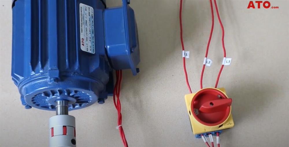
How to Wire 3phase Induction Motor?
The most common type of three-phase motor is that which has nine labeled (and often colored) wires coming out of the box on the side. There are many motors with more or fewer wires, but nine is the most common. These nine-wire motors may be internally connected with either a Wye (star) or a Delta configuration, established by the manufacturer.
How does an AC Motor Work? Its Purpose
A 3-phase motor works by harnessing three alternating currents to produce a rotating magnetic field, which, in turn, drives the motor's rotor and induces rotation. This design enhances efficiency and performance, making 3-phase motors suitable for a wide range of industrial applications.
Three Phase Motor Wiring Diagram Cadician's Blog
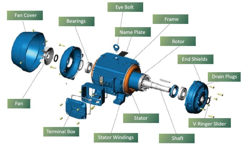
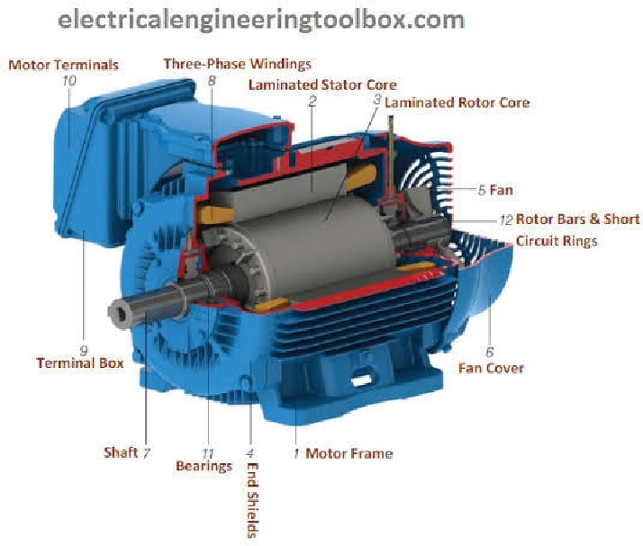
Diagram, Working & Types In this topic, you study Three Phase Induction Motor. Three Phase Induction Motor (Fig. 1) consists of a set of three phase windings distributed in slots around the stationary outer member called stator. The rotating member which is known as rotor also carries the other set of windings.

3 Phase Motor Control Panel Wiring Diagram Home Wiring Diagram
Wiring Diagrams for Three-phase Motors. For most projects, it really doesn't matter what the internal wiring setup might be. If you have a five HP motor wired for high voltage, that motor is appropriate for any 480-volt application that needs five horsepower. You don't need to worry about how the manufacturer bonded the wires inside.
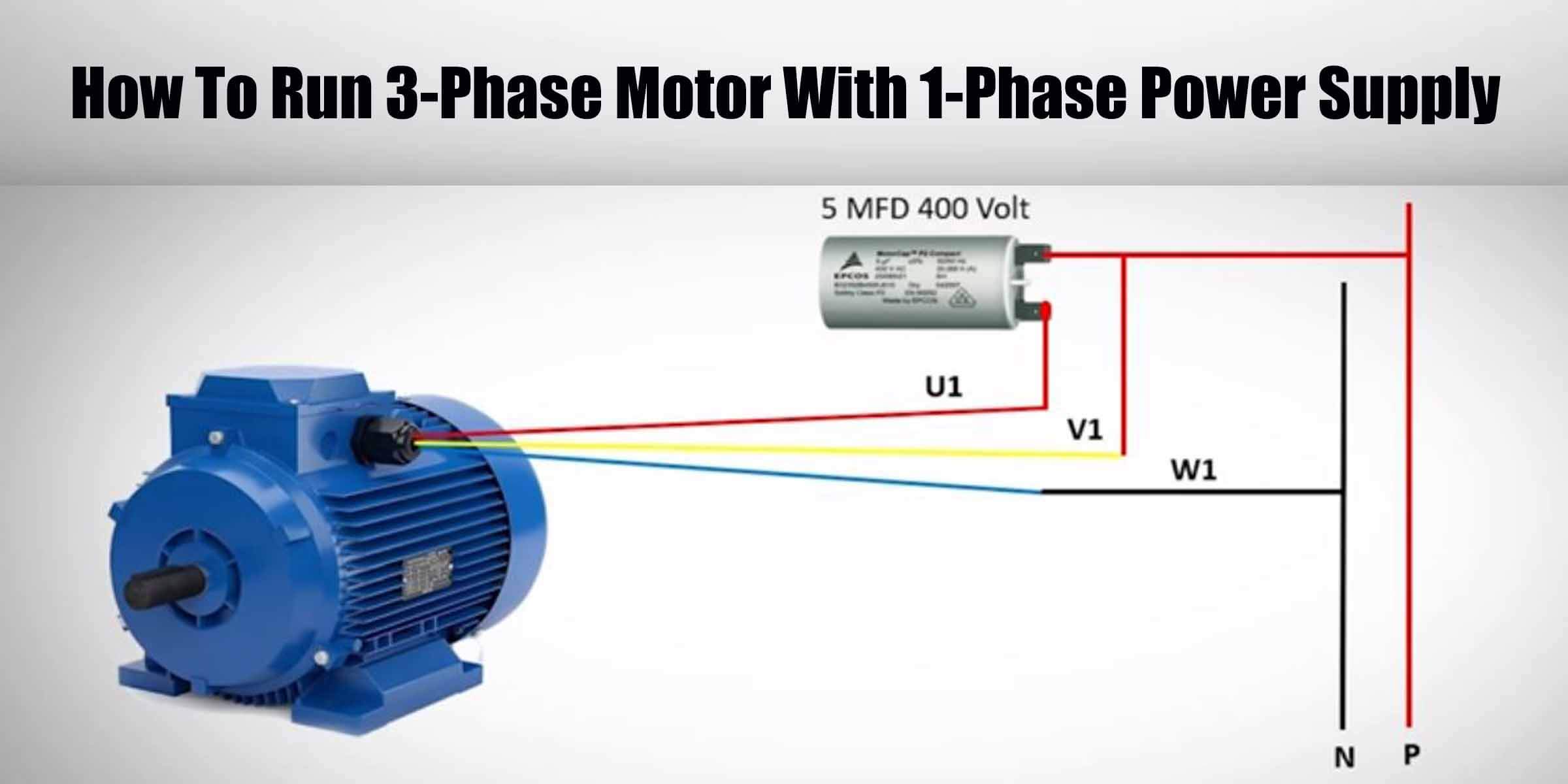
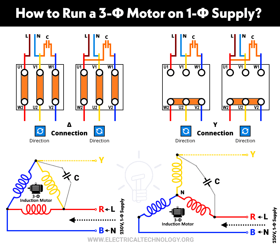
Running a Threephase electric motors on singlephase power
Capacitor Motor Single-Phase Wiring Diagrams ALWAYS USE WIRING DIAGRAM SUPPLIED ON MOTOR NAMEPLATE. W2 CJ2 UI VI WI W2 CJ2 UI VI WI A cow VOLTAGE Y HIGH VOLTAGE z T4 Til T12 10 Til T4 T5 ALI L2 T12 TI-BLU T2-WHT T3.ORG T4-YEL T5-BLK T6-GRY T7-PNK T8-RED T9-BRK RED TIO-CURRY TII-GRN T12-VLT z T4 Til T12

3 Phase Motor Wiring Connection
ALWAYS USE WIRING DIAGRAM SUPPLIED ON MOTOR NAMEPLATE Three Phase - 12 Lead Motor Three Phase - 9 Lead Motor Three Phase - 6 Lead Motor Three Phase - 3 Lead Motor 3 comments Find 3 Phase Electric Motor Wiring Diagrams for 12-Lead Motors, 9-Lead Motors, 6-Lead Motors, and 3-Lead Motors here.

Rewinding 3 Phase Motor 54 Steps (with Pictures) Instructables
In conclusion, the circuit diagram of a three-phase induction motor consists of a power supply, stator windings, rotor windings, and motor control circuitry. These components work together to generate a rotating magnetic field and convert electrical energy into mechanical energy. Understanding the circuit diagram is crucial for troubleshooting.

Circuit model of a threephase wyeconfigured motor. Download
The wiring diagram for a 3 phase motor is a visual representation of how the motor is connected to the power supply. It shows the connections between the power source, the motor windings, and the control circuitry. By understanding the wiring diagram, technicians and electricians can properly install and troubleshoot 3 phase motors.
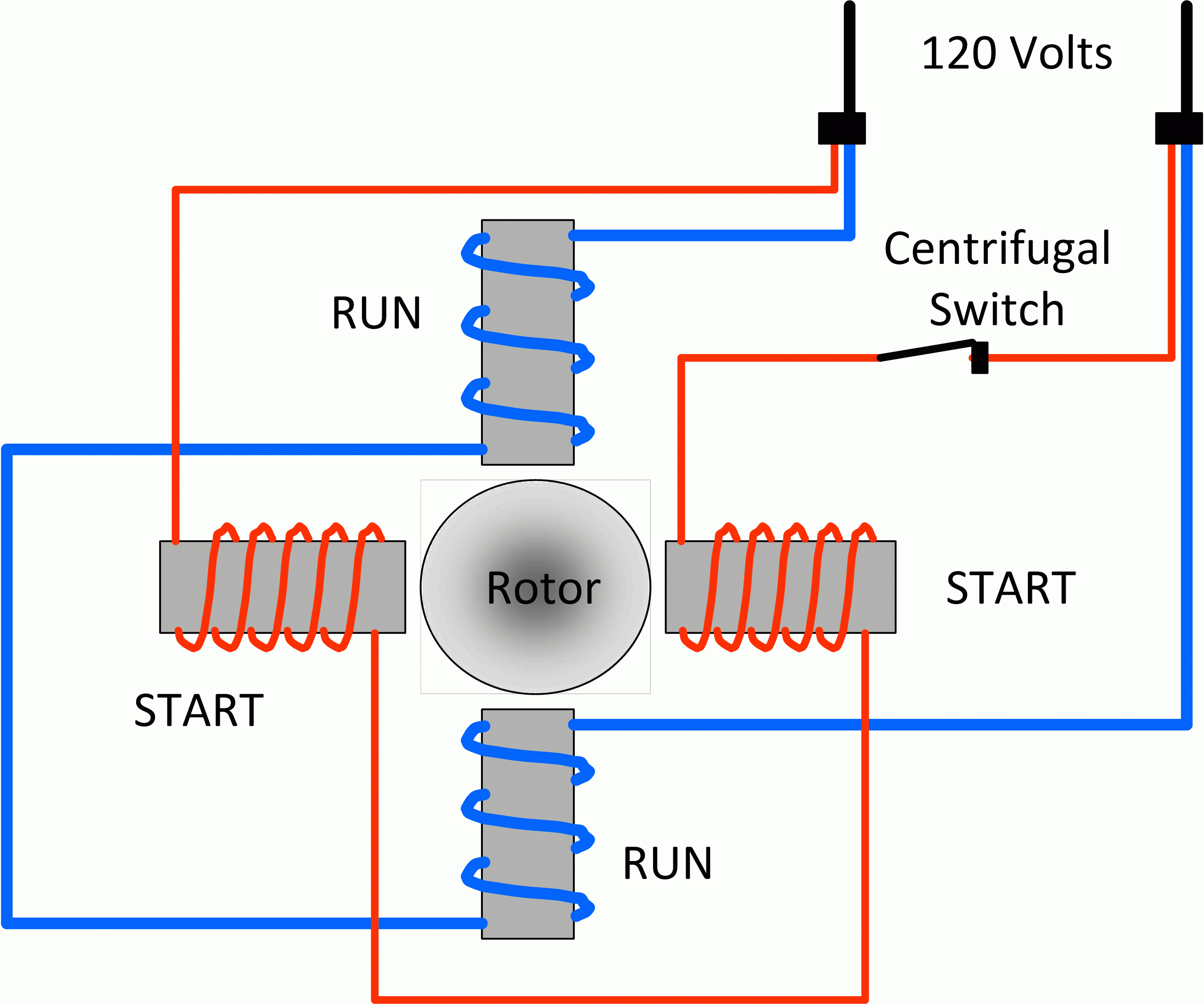
What happens if You Connect a 3Φ Motor to 1Phase Supply?
Diagrams 23 Motor-Lead Connections Three-phase motors use coils of wire to create magnetic fields and produce rotation. Standard 3-phase motors use six individual coils, two for each phase. The internal construction and connection of these coils inside of the motor is predetermined when the motor is manufactured.
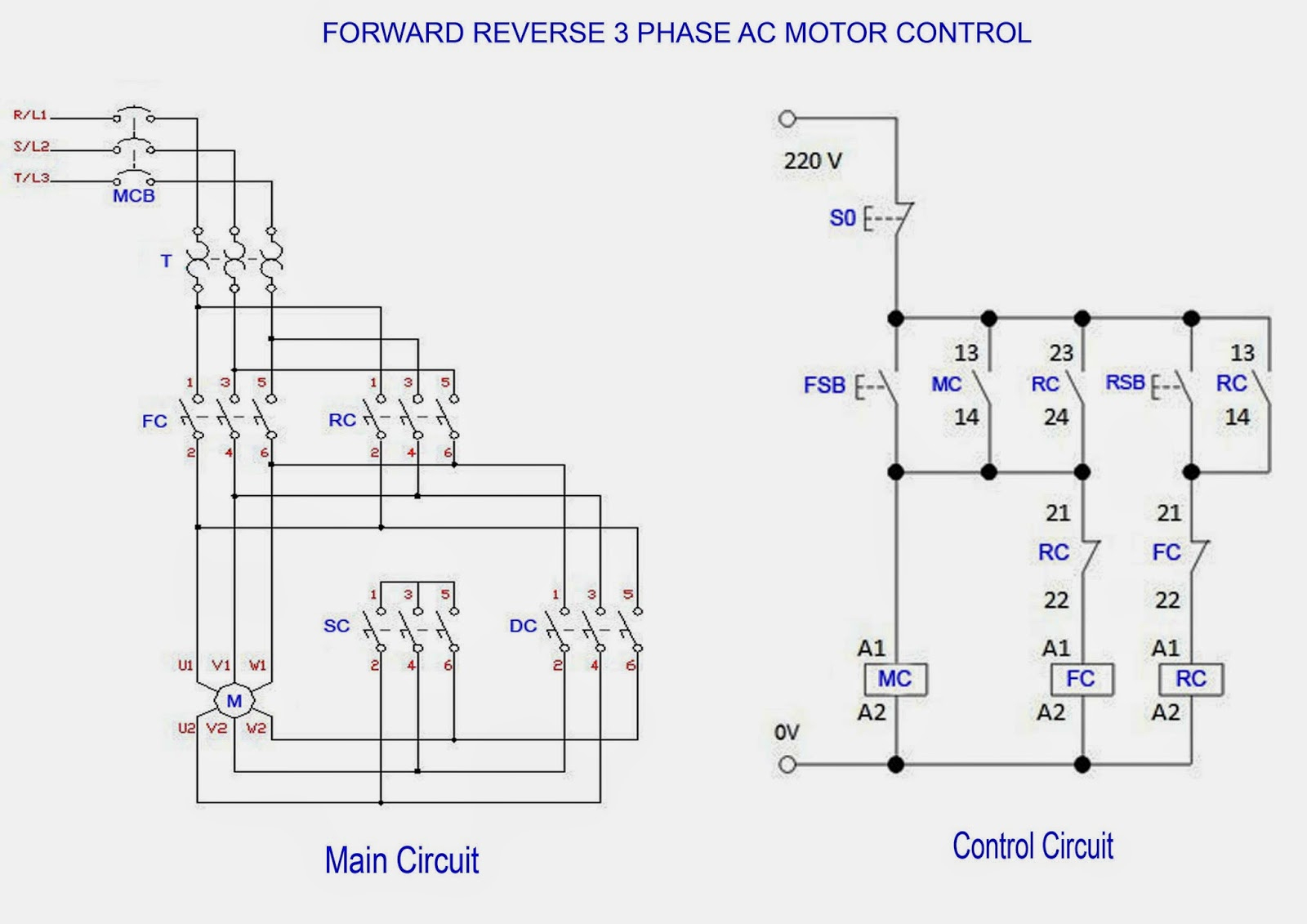
Direct Online Starter Animation Diagrams Electrical Online 4u
What is a 3 Phase Motor? A three-phase motor is a type of electric motor that operates on three alternating current (AC) power lines. It is commonly used in industrial and commercial applications for its efficiency, reliability, and power output.

3 phase motor wiring Wire, Diagram, Motor
A three phase induction motor is a type of AC induction motors which operates on three phase supply as compared to the single phase induction motor where single phase supply is needed to operate it.

3 Phase Motor Wiring Diagram Wiring Harness Diagram
Understanding the wiring diagram. When working with a 3-phase motor, it is essential to understand the wiring diagram to ensure proper installation and operation. The wiring diagram is a visual representation of how the motor is wired, including the connections between the motor windings and the power source.

Schematic diagram of a three phase BLDC motor drive Download
1. In case it is having star delta starter than they are started as Star connected motor. 2. After it attains 80% of synch speed the changeover takes place from star to original configuration delta. 3. In star the voltages across the windings are lesser that is 1/1.732 times that available in delta so current is limited.
